TITLE IV ONSITE WASTEWATER
MANAGEMENT CODE
CHAPTER 4.15 DESIGN STANDARDS: ALL SYSTEMS
Return to Title IV Table of ContentsSections:
4.15.010 General4.15.050 Design Practices
4.15.060 Construction Practices
4.15.100 Site Criteria - Setbacks
4.15.111 Depth to Groundwater
4.15.121 Soil Depth
4.15.131 Minimum Percolation Rate
4.15.141 Ground Slope
4.15.161 Cover Fill Systems
4.15.181 Drainage Improvements
4.15.200 Site Evaluation
4.15.203 Designer Required
4.15.205 Wet Weather Testing Period
4.15.206 Wet Weather Groundwater Tests
4.15.207 Wet Weather Percolation Tests
4.15.221 Soil Profile
4.15.224 Percolation Testing
4.15.225 Percolation Test Procedures
4.15.230 Groundwater Mounding Analysis
4.15.235 Nitrate Loading Analysis
4.15.240 Repair and Replacement Systems - Previous Site Evaluation
4.15.300 Septic Tank Construction and Size
4.15.310 Septic and Sump Tank Design Standards
4.15.320 Septic Tank Installation
4.15.330 Connections to Septic Tank
4.15.600 Dispersal Field Design
4.15.603 Trench Layout
4.15.621 Design Flow
4.15.625 Drainage Improvements
4.15.630 Surface Flows
4.15.635 Subsurface Flows
4.15.640 Dispersal Fields
4.15.650 Pressure Dosed Distribution
4.15.660 Serial Distribution
4.15.670 Sizing for Standard and Pressure Distribution Dispersal Fields
4.15.680 Trench Dimensions
4.15.690 Depth of Trench
4.15.700 Effective Wall Trench
4.15.705 Chambers
4.15.710 Trench Tolerance
4.15.720 Trench Width
4.15.730 Required Cover
4.15.740 Pumps or Dosing Siphons
4.15.750 Sump/Pump Tanks
4.15.760 Hydraulic Design for Pressure Distribution Systems
4.15.770 Diversion Valve
4.15.780 Monitoring Wells
4.15.790 Piping
4.15.800 Pressure Piping
4.15.810 Thrust Blocks
4.15.820 Gravel
4.15.830 Filter Fabric
4.15.900 Use of Intermittent Sand Filters
4.15.910 Site Criteria
4.15.930 Leach Field Sizing for Intermittent Sand Filter Systems
4.15.940 Intermittent Sand Filter Design Standards
4.15.950 Intermittent Sand Filter Design Flow
4.15.960 Leach Field Design: General
4.15.970 Raised-Bed Leach Field Design
4.15.980 Maintenance Program and Maintenance Design Features
4.15.990 Maintenance Design Features
4.15.995 Maintenance Program
4.15.010 General
Standard systems shall be designed and constructed as provided for in this chapter. Except where
otherwise indicated, the design standards shall apply uniformly to wastewater treatment systems
constructed to serve new construction and to the repair and replacement of an existing system.
Where the standards differ, it is the intent of the District that to the extent reasonably possible, a
design should conform to standards for new construction.
4.15.050 Design Practices
In addition to the provisions of this code, and where not contrary to this code, the wastewater
treatment system design practices accepted by the District may be found in the Minimum
Guidelines and the Design Manual.
4.15.060 Construction Practices
In addition to the provisions of this code, and where not contrary to this code, the wastewater
treatment system construction practices accepted by the District may be found in the Minimum
Guidelines, the Design Manual, and the most current edition of the Uniform Plumbing Code as
published by the International Association of Plumbing and Mechanical Officials adopted by the
County of Marin.
4.15.100 Site Criteria - Setbacks
Minimum horizontal distances between other site features and the septic tank and the edge of the
drain field shall be as follows:
| Site Feature | Septic Tank | Dispersal field |
| Buildings | 5 feet | 10 feet |
| Property Line | 5 feet | 5 feet |
| Downslope Property Line | 10 feet | 25 feet (Note 1) |
| Wells (domestic or non-domestic) | 100 feet | 100 feet |
| Watercourses & Water Bodies | 50 feet (Note 4) | 100 feet |
| Drainage ways | 50 feet | 50 feet |
| Cut or Embankment or Bluff | 10 feet | (Note 2) |
| Unstable Land Forms | 50 feet | 50 feet |
| Swimming Pools/Hot Tubs | 10 feet | 15 feet |
| Public Water Main (Domestic) | 10 feet | 10 feet |
| Water Laterals | (Note 3) | (Note 3) |
| Driveway/Parking/Paved Area | (Note 5) | 5 feet |
| Septic Tank/Sump Tank/Pretreatment Unit | 5 feet |
4.15.111 Depth to Groundwater
The minimum depth to the highest seasonal elevation of the groundwater from the bottom of the
dispersal field trench shall be as follows:
| Percolation Test Rate | Depth |
| Slower than 5 minutes per inch | 3 feet |
| Faster than 5 minutes per inch | 20 feet* |
* except where soil profile justifies a lesser depth or for use of a District approved pretreatment device
The soil depth requirements listed above refer to the natural composition of the existing soil. It is not permissible to import soil to meet minimum depth requirements to groundwater, except pursuant to Sections 4.15.910 (Site Criteria) and 4.15.970 (Raised-Bed Leach Field Design).
4.15.121 Soil Depth
The minimum depth of suitable soil below the bottom of the drain field trench shall be three feet.
The soil depth requirement refers to the natural composition of the existing soil. It is not
permissible to import soil to meet the minimum depth requirement except pursuant to
Sections 4.15.910 (Site Criteria) and 4.15.970 (Raised-Bed Leach Field Design).
4.15.131 Minimum Percolation Rate
The percolation rate of soils in the treatment area shall not be slower than 120 minutes per inch.
4.15.141 Ground Slope
Where the proposed leach field ground slope exceeds 20%, the design submittals shall be
accompanied by a geological engineering report demonstrating that the proposed design will not
create a public health hazard or jeopardize the building site or contiguous properties. The ground
slope criteria refers to the existing landform. It is not permissible to grade to achieve a reduction
in ground slope.
4.15.161 Cover Fill Systems
Where soil and/or groundwater conditions require shallow trench placement, soil fill may be used
to satisfy dispersal field cover requirements. Such fill systems shall comply with all system
requirements as well as the following:
- The maximum allowable ground slope shall be 18%.
- The percolation rate shall not be slower than 60 minutes per inch.
- The drain rock and perforated pipe sections shall be installed entirely within native soil.
- Prior to placement of fill material, all vegetation shall be removed and the ground surface disked or plowed to permit good mixing of native soil and fill material.
- Sand, gravel, or rock may not be used for cover fill. The soil used for fill shall be similar in texture to the native soil.
- Fill shall be placed in layers of not more than eight inches and compacted to approximately the same dry density as the native soil. Alternative compaction procedures may be allowed in accordance with recommendations and technical data supplied by a designer.
- The fill shall be continuous, constructed to a uniform depth over the dispersal fields as specified in Section 4.15.151, shall extend a minimum distance of 15 feet in any direction from the center of any trench, and shall be completed with a toe tapered at no less than a 5:1 ratio.
4.15.181 Drainage Improvements
Surface and sub-surface drainage waters may not be artificially diverted from the dispersal field
area except as provided in Sections 4.15.625.
4.15.200 Site Evaluation
Site evaluations shall be performed on all parcels for which a wastewater treatment system is
proposed. A site evaluation shall include a profile inspection and percolation testing.
4.15.203 Designer Required
Site evaluations, and the designs based thereon, shall be performed by, or performed under the
direct supervision of a designer.
4.15.205 Wet Weather Testing Period
The wet weather period shall be determined annually by the General Manager between January
1st and May 1st after 50% of the average annual rainfall has fallen. Average annual rainfall
measurement begins on the previous first day of July. If 50% of the average annual rainfall has
not fallen or a rainfall of 0.8 inches in a 48 hour period does not occur between January 1st and
May 1st, then the wet weather testing period will not open.
4.15.206 Wet Weather Groundwater Tests
Wet weather determination of groundwater levels shall be required within the Special Flood
Hazard Area except when the District Engineer has determined that there is adequate
documentation of groundwater levels. Wet weather determination of groundwater levels outside
the Special Flood Hazard Area shall be determined during the soil profile investigation with the
District Engineer. This determination will be based on the presence of clayey soils (greater than
30% clay) with high shrink-swell potential (plasticity index greater than 20 ASTM D4318-84).
Wet weather groundwater testing shall occur within the wet weather testing period ten (10) calendar days following a rainfall of 0.8 inches in a 48-hour period. A minimum of three (3) groundwater level inspections shall be made by District staff. The owner shall install a minimum of two (2) monitoring wells, one in each of the proposed leach fields. The monitoring well shall be a 2" to 4" diameter slotted or perforated pipe installed 3 feet below the proposed bottom of the leach field. Upon installation of the monitoring wells, submittal of the Site Review application, and payment of the Site Review fee, the owner shall notify the District to commence groundwater testing.
4.15.207 Wet Weather Percolation Tests
Wet weather percolation testing shall be determined by the District Engineer based on the
presence of clayey soils (greater than 30% clay) with high shrink-swell potential (plasticity index
greater than 20 ASTM D4318-84) during the soil profile investigation. Wet weather percolation
testing shall occur within the wet weather testing period (See Section 4.15.225 for percolation test
procedures).
4.15.221 Soil Profile
Soil conditions shall be evaluated by direct inspection of the soil profile of the primary and
secondary treatment areas, using backhoe excavations, hand auger, and/or core sampling. The
soil profile shall be inspected to a depth of at least three feet below the bottom of the proposed
treatment system. At least one backhoe excavation or two borings in each of the primary and
reserve area is required. Information provided from the profile shall include the following:
- Thickness, depth, and texture of soil layers encountered;
- Depth to bedrock, hardpan, or other impermeable layer;
- Depth to groundwater;
- Evidence of soil mottling; and
- Other conditions affecting the potential use of the soil for sewage treatment including, but not limited to, evidence of roots, fissures, dampness, structure, and stoniness. Depth to groundwater shall be determined during a wet weather testing period, except in areas determined by the General Manager to have adequate documentation of groundwater conditions.
The soil profile and textural requirements specified refer to the natural composition of the existing soil mantle. It is not permissible to import soil to meet textural requirements.
4.15.224 Percolation Testing
Percolation tests shall be conducted to determine the design loading rate. Such tests shall be
conducted in the wet weather testing period when the treatment areas are determined from soil
profile information or other information to have clayey soils (greater than 30% clay) with high
shrink-swell potential or potential soil saturation problems. All percolation test procedures shall
follow the procedures specified in Section 4.15.225. The District may determine that a percolation
test is not required in cases where the system's proposed location is in sandy or non-cohesive
soils.
4.15.225 Percolation Test Procedures
Percolation tests shall be scheduled with, and attended by, SBCWD personnel. The applicant
shall allow forty-eight hours for scheduling of the percolation test(s). Percolation tests are to be
carried out in soils in their native state at the proposed depth of the soil absorption field and at
lesser depths. A minimum of six passing tests shall be required for each property as depths
respective to the effective wall of the dispersal trench. Three of the passing percolation tests shall
be conducted at the proposed trench depth or deeper. Percolation tests may be conducted at the
bottom of backhoe or other excavation holes where deeper testing is required. Additional
percolation testing or textural analysis of deeper soil zones may be required to determine if
underlying soils have adequate permeability.
Individual tests shall be run in six-inch diameter holes dug or bored using hand tools. If power- based tools are used, any smeared soil surfaces shall be removed from the sides of the hole. Loose material shall be removed from the bottom of the hole and two inches of fine gravel shall be added to protect the bottom from scouring.
If soils tend to collapse, a perforated pipe shall be placed in the hole and carefully packed gravel shall be placed between the pipe and the hole wall. Where gravel pack is needed, the percolation rate shall be adjusted for the water displacement attributable to the gravel and perforated pipe. The adjustment factor shall be computed based upon determination of the actual percentage of void space in the gravel pack portion of the test hole.
Presoaking is required in all tests. The water shall be carefully placed within the hole. Water shall be added to at least a twelve-inch (12") depth over the gravel and maintained at this level for at least four hours, preferably overnight. If the soil is known to have a low shrink-swell potential (clay content 15% or less) testing may proceed after the four hour presoak for a minimum of four hours.
Soils with higher shrink-swell potential are to be tested the following day and in any case within 24 hours of presoaking as follows:
- Fill the hole with clean water (no chemical additives) approximately six inches above the gravel (or eight inches above the bottom of the hole).
- Using a secure fixed reference and timepiece to determine the time for the water to recede one inch or determine the drop of water after an interval of 30 to 60 minutes.
- Refill, record information, and repeat the process. Test for a minimum of two hours if rates have stabilized. Stabilized rates shall be two consecutive rates in minutes per inch within 10% of each other. If rates have not stabilized in two hours, continue testing until such time that rates stabilize. If rates do not stabilize at four hours, discontinue testing.
- Use the last water level drop to calculate the percolation rate.
- Time lapse between test intervals shall be a minimum of five to ten minutes.
- Test results shall reported in units of minutes per inch.
The percolation test rate shall be determined by averaging at least six passing tests conducted in or near the proposed drain field of which at least three of the test holes will be at the bottom depth of the proposed drain field. This average shall be used for determining the appropriate loading rate from the table in Section 4.15.670.
4.15.230 Groundwater Mounding Analysis
An analysis of the localized groundwater mounding shall be prepared for parcels within the
Special Flood Hazard Area if all of following conditions exist:
- Groundwater is within 36 inches from existing grade, and;
- Proposed septic system is located on a parcel size with less than 5,000 ft2, and;
- Proposed septic system is located within 50 feet to an existing septic system.
The groundwater mounding analysis shall demonstrate a 36 inch minimum vertical separation from groundwater to the leach field.
4.15.235 Nitrate Loading Analysis
An analysis of the nitrate loading shall be prepared for parcels within the Special Flood Hazard
Area if all of following conditions exist:
- Groundwater is within 36 inches from existing grade, and;
- Proposed septic system is located on a parcel size with less than 5,000 ft2, and;
- Proposed septic system is located within 50 feet to an existing septic system.
The nitrate loading analysis shall demonstrate the proposed septic system shall not exceed the localized nitrate concentration beyond 10 mg/L.
4.15.240 Repair and Replacement Systems - Previous Site Evaluation
Where the District has on file the soil profile, and percolation test information described above on
an existing wastewater treatment system, the General Manager may waive the requirement to
obtain new information prior to designing or carrying out repairs or installing a replacement
system.
4.15.300 Septic Tank Construction and Size
Septic tanks shall be constructed as provided in Appendix I of the Uniform Plumbing Code
excepting that steel tanks are prohibited. No septic tank shall be smaller than 1,500 gallons and
shall be equipped with an effluent filter of an approved type. Unless approved by the District
Engineer for use with a traffic rated tank, tank lids shall not weigh more than 25 pounds and must
be securely fastened to access risers of an approved type. All maintenance covers shall be
removable and shall be gas and watertight.
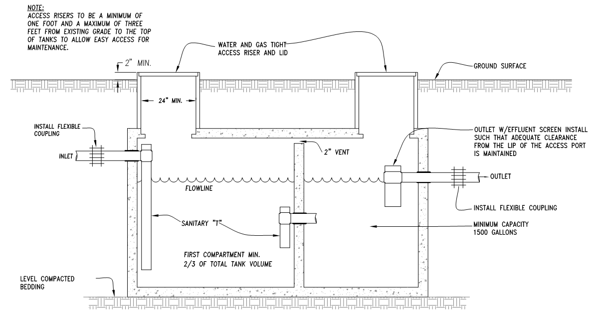
TYPICAL SEPTIC TANK DETAIL
4.15.310 Septic and Sump Tank Design Standards
All tanks shall meet all of the following design standards:
- The septic tank capacity shall be equal to at least three times the maximum daily design flow, or 1,500 gallons, whichever is larger.
- The sump tank capacity shall be equal to 100% of the daily maximum flow and dose volume.
- If a pump is utilized in a sump tank, it shall have a 1/8" screen and be capable of delivering the design volume of effluent to the sand filter based upon design head; controls shall be of an approved type and shall include an approved elapsed time meter and a dose counter for providing information sufficient to verify compliance with design flow standards; an alarm system of an approved type shall be installed to provide a visual and audible warning that effluent in the secondary tank is in the capacity reserved for emergency storage.
- All traffic rated tanks, risers, and covers shall be capable of supporting 20 tons and meet Uniform Plumbing Code requirements.
- The septic and sump tank shall be constructed of either District approved concrete, fiberglass, or plastic.
- Unless approved by the District, fiberglass and plastic tanks shall not be installed within the Special Flood Hazard Area. Approval of the fiberglass and plastic tanks may be granted on case by case basis due to limited or no access to the tank location.
4.15.320 Septic Tank Installation
Septic tanks shall be installed such that access ports or openings are at least twelve inches
below grade with risers which reach two (2) inches minimum above the ground surface. Septic
tanks shall be installed level on a solid bed and in no case shall the depth be greater than the
manufactures limits of cover. Soil around the tank shall be hard-compacted or jetted. District
approved access risers and lids shall be installed.
4.15.330 Connections to Septic Tank
Connections to a septic tank shall be made in a manner consistent with the Uniform
Plumbing Code.
4.15.600 Dispersal Field Design
Except as otherwise provided herein, the design and installation of the dispersal field to serve new
construction shall conform to the provisions of the Minimum Guidelines and, where not in conflict
with said Minimum Guidelines, the Uniform Plumbing Code.
4.15.603 Trench Layout
Trenches shall be placed on contour, perpendicular to groundwater flow patterns. Layout shall
maximize the spreading of effluent in the dispersal field area. No single trench shall be more than
one hundred (100) feet in length.
4.15.621 Design Flow
Notwithstanding the number of Bedrooms within a single dwelling unit, the minimum dispersal field
area shall be based upon total floor area of habitable space and upon the following wastewater
generation rates.
| Dwelling Unit Total Floor Area |
Peak Flow Per Day |
Average Flow Per Day |
| 0 to 1400 square feet | 150 | 100 |
| 1401 to 1900 square feet | 300 | 200 |
| 1901 to 2800 square feet | 450 | 300 |
| 2801 to 3300 square feet | 600 | 400 |
The designer may design the dispersal area for greater discharges; however, peak, and average flows may not deviate from the above table. The flow of water to the septic system will be monitored. Flows in excess of the above rates may result in a citation being issued to the property owner. Failure by the owner to assure flows do not exceed the above rates may result in the termination of water service to the property and/or revocation of the wastewater discharge permit. Where peak flows are designed to be in excess of 600 gallons per day or average daily flows are designed to be in excess of 400 gallons per day, the design standards shall be considered a variance in accordance with Section 4.19.050.
4.15.625 Drainage Improvements
Surface and sub-surface drainage shall be diverted away from the dispersal field area.
4.15.630 Surface Flows
Any concentrated drainage flow from buildings, yards, drives, etc., shall be diverted away from the
dispersal field area. This may require site grading and installation of a diversion ditch or berm on
the upslope side of the drain field area.
4.15.635 Subsurface Flows
The use of intercept drains to lower the level of perched groundwater in the immediate drain field
area shall be acceptable under the following conditions:
- Natural ground slope is greater than 5%.
- Site investigations show groundwater to be perched on a clearly definable layer of bedrock, hardpan or impermeable soil.
- The intercept drain shall be installed on the upslope side of the leach field area.
- The intercept drain shall be a minimum of twelve inches wide and shall extend from the ground surface into bedrock, hardpan, or the impermeable soil layer a minimum of six and a maximum of 96 inches (eight feet), provided no hardpan or impermeable soil is encountered.
- Pervious sections of the intercept drain shall be separated from the leach field and
septic tank as follows:
- Up slope minimum of 15 feet
- Lateral minimum of 25 feet
- Downslope minimum of 50 feet
- The bottom and downslope side of the intercept drain shall be lined with plastic film having a minimum thickness of 12 millimeters.
- The drainage trench shall be filled with 3/4 to 1-1/2 inch drain rock, with perforated four inch drainpipe along and two inches above the bottom of the trench.
- Filter fabric or other suitable filter material shall be placed immediately above the drain rock.
4.15.640 Dispersal Fields
All dispersal field designs shall have two fields, each of which are 100 percent of the design
loading with an approved diversion valve or valves between each field.
4.15.650 Pressure Dosed Distribution
Pumped pressure dose distribution designs require the average percolation rate be between 6
and 120 minutes per inch. A District approved pretreatment device, as defined in
Section 4.03.260, or greater separation to groundwater, as listed in
Section 4.15.111, shall
be required for average percolation rates faster than 5 minutes per inch.
Pressure dosed distribution piping shall have:
- 1.25" minimum inside pipe diameter
- 1/8" minimum orifice diameter
- Orifice shields for upward holes
- Gate valves to adjust the orifice squirt height
4.15.660 Serial Distribution
Serial distribution (gravity flow) systems require the average percolation rate between 6 and 60
minutes per inch.
4.15.670 Sizing for Standard and Pressure Distribution Dispersal Fields
Dispersal fields shall be sized based on the minimum soil loading rate shown on the table below.
This table gives the relationship for average percolation rate of six or more holes and the design
loading rates. Percolation faster than 1 minute per inch or slower than 120 minutes per inch shall
not be included within the average percolation rate.
| Average Percolation Rate Min/inch |
Design Loading Rate Gal/ft²/Day |
| Less than 1 | system prohibited |
| 3 | 1.2* |
| 10 | 0.8 |
| 24 | 0.6 |
| 30 | 0.56 |
| 45 | 0.45 |
| 60 | 0.35 |
| 90-120 | 0.2 |
| >120 | system prohibited |
4.15.680 Trench Dimensions
Trench spacing shall be no less than six feet from center of one trench to the center of the
neighboring trench. Areas with slopes greater than 20 percent shall have minimum trench
spacing as follows:
| Slope | Minimum Trench Spacing |
| 0-20% | 6 feet |
| 21-25% | 7 feet |
| 26-30% | 8 feet |
| 31-35% | 9 feet |
| >36% | 10 feet |
4.15.690 Depth of Trench
Depth of the trench is determined in part by the depth of the percolation test depths required in
Section 4.15.225. The bottom of trench shall maintain a three foot separation to impermeable
soils and seasonal high groundwater conditions as required in Section 4.15.111.
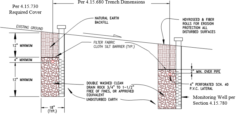
TYPICAL TRENCH SECTION
4.15.700 Effective Wall Trench
The effective wall trench section is the area measured from below the perforated lateral to the
bottom of the trench.
4.15.705 Chambers
The effective infiltrative surface shall be considered to be the trench sidewall area between the top
of louvered sidewall and trench bottom.
4.15.710 Trench Tolerance
Trenches for dispersal fields are to be laid along contours with a tolerance of no greater than three
inch deviation in 100 feet of trench bottom.
4.15.720 Trench Width
Trenches shall be 18 to 36 inches in width for pressure dosed distribution and serial distribution system.
4.15.730 Required Cover
Cover requirements vary based on the slope of the dispersal field. The cover slope requirements
from the ground surface to the top of drain rock shall be as follows:
| Leach Field Slope (%) |
Cover Requirements for Gravity System 1 - 120 MPI |
Cover Requirements for Pressure Dosed Systems 1 - 30 MPI |
Cover Requirements for Pressure Dosed Systems 31 - 120 MPI |
| 0-10 | 12" | 12" | 12" |
| 11-15 | 18" | 12" | 12" |
| 16-20 | 24" | 12" | 12" |
| 21-30 | 30" | 15" | 18" |
| 31-40 | n/a | 18" | 24" |
| > 40 | n/a | 24" | 30" |
4.15.740 Pumps or Dosing Siphons
If a pump or dosing siphon is utilized to pressurize a dispersal field, the pump or siphon shall be
compatible for use with sewage.
4.15.750 Sump/Pump Tanks
All sump/pump tanks shall meet the following conditions:
- An external pump basin as per Section 4.15.310 shall be installed which shall provide emergency storage for at least 100% of the maximum daily design flow and which shall be accessible for inspection.
- Access shall be provided by a minimum 24-inch access hole.
- All pipes and/or electrical conduits through the sump shall be either precast into the sump or sealed with gas-tight compression connectors.
- All maintenance covers shall be removable, shall be gas and water tight, and shall weigh less than 25 pounds.
- The following electrical features shall be provided:
- An outdoor-type control box containing fused disconnects and motor protection switch.
- A control box shall be mounted on the building served if located within 20 feet of the sump, otherwise the control box shall be mounted on a pipe stand or wooden post. The control box shall be visible to the road way or as approved by the District Engineer.
- Electrical conduit shall be PVC. Separate conduits shall be provided for control wire and power supply.
- The pumping system shall be installed with a 1/8" screen in the basin.
- Controls shall be of an approved type and shall include approved elapsed time meters and dose counters; an alarm system of an approved type shall be installed to provide a visual and audible warning that effluent in the basin is in the capacity reserved for emergency storage.
- A hands off automatic function.
- The panel shall coordinate mechanical floats for on-off and alarm conditions.
- The bottom of the pump shall be set a minimum of four inches above the sump bottom.
- Aside from the construction permit, the owner shall be responsible for additional permit(s) required by the Marin County Building Division for all pump installations.
4.15.760 Hydraulic Design for Pressure Distribution Systems
All pressure distribution type systems will have either a pump or a dosing siphon to regulate the
size of discreet doses. The dose size should be adequate to insure that the dispersal field will
pressurize but as small as possible in order to provide small and frequent dosing of the fields.
Where topography will allow gravity flow from the septic tank to the dispersal field, a dosing siphon
may be utilized provided a method of counting the doses and an audio/visual alarm is included in
the control panel. The pump shall be of the size and type to accommodate the intended use.
4.15.770 Diversion Valve
All dual dispersal field systems shall be provided with a pressure-rated PVC diversion valve. The
valve shall be housed in a box that terminates above grade and is accessible for inspection.
4.15.780 Monitoring Wells
All trench systems are required to have two monitoring wells, at the ends of the trench, installed to
the depth of the trench. Monitoring wells shall include a 12 inch deep seal of concrete or
bentonite to preclude surface water infiltration to the trench. The monitoring well shall have
slotted or drilled holes within the effective sidewall area.
TYPICAL MONITORING WELL DETAIL
4.15.790 Piping
All pipe throughout the septic system should be schedule 40 or better, sized to accommodate the
flows anticipated.
4.15.800 Pressure Piping
The pipe from the sump to the dispersal field shall be solid plastic, schedule 40, and sized to meet
pumping and effluent flow requirements while minimizing frictional losses. Starting at the pump
installation, a union, a swing check valve, and a double wedge gate valve shall be mounted.
These items are required either in the sump or adjacent to the sump or in a concrete box.
4.15.810 Thrust Blocks
Concrete thrust blocks are required at all bends greater than 45 degrees.
4.15.820 Gravel
The gravel utilized in the dispersal field trenches shall be clean (free of fines) and durable sized
from 1/4" to 1 1/2 ".
4.15.830 Filter Fabric
Filter fabric is required between the gravel and cover in the leach lines to reduce the migration of
fines into the gravel of the trenches.
4.15.900 Use of Intermittent Sand Filters
A wastewater treatment system using an intermittent sand filter may be used for new construction.
4.15.910 Site Criteria
Site criteria for all intermittent sand filter systems designs, whether for new construction or for
replacement of an existing system, shall be the same as the site criteria for standard systems,
except as follows:
- The measured depth to groundwater shall be at least 24 inches below the existing grade (to achieve the 3 foot depth-to-groundwater requirement a raised-bed leach field may be used).
- For new construction the soils shall be homogeneous sand.
- Setback requirements for sand filter system components shall be as
specified in Section 4.15.100. Sand filters shall have the same setbacks as
septic tanks except as follows:
- Building to leach field: 5 feet
- Adjoining property line to leach field: 5 feet.
- Driveways, parking areas, or paved areas to leach field: 1 foot with approved barrier
4.15.930 Leach Field Sizing for Intermittent Sand Filter Systems
Leach fields shall be sized based on the minimum soil loading rate shown on the table below.
This table gives the relationship for average percolation rate of six or more holes and the design
loading rates.
| Leach Field Requirements For Intermittent Sand Filter Systems, Percolation | |||
|
Percolation Rate (MPI) |
Leach Field Design |
Design Loading Rate (gpd/ft2/day) |
Minimum Soil Depth1 (ft) |
| < 5 | Serial Distribution or Pressure Dose Distribution (PD) | 2.4 | 3 |
| Raised Bed | 1.4 | 2 | |
| 5 to 90 | Serial Distribution or PD | 2.0 x DLR 2 | 3 |
| 91 to 120 | Serial Distribution or PD | 0.3 | 3 |
2DLR = design loading rate per Section 4.15.670
4.15.940 Intermittent Sand Filter Design Standards
Intermittent sand filters shall be designed based upon the following standards:
- The design shall be based upon a design loading rate of 1.23 gallons per square foot per day.
- Depth of cover shall not exceed 12 inches.
- Filter fabric shall be of an approved type and design.
- Distribution bed gravel shall be double-washed pea gravel free of fines; the distribution bed below the piping shall be at least 4 inches deep.
- The distribution bed piping shall be Schedule 40 PVC sized so that there is no more than a 2% differential in discharge head with head loss calculations based upon an approved method presented with the design submittals; the pipe shall be laid flat with orifices pointing upward and shall be pressure tested to ensure the integrity of all joints; the orifice shall be 1/8"; orifice shields shall be provided. To provide for more effective utilization of sand bed, orifices shall be spaced on average so that there is four square feet of bed per orifice. An approved valve may be provided to alternately dose at least two sections of the bed. Orifices shall be pre-drilled on a drill press or other approved alternative.
- The filter bed sand shall be a minimum of two feet deep and the
sand shall meet the following criteria:
Sieve
SizePercent
Passing#4 100 #8 70-90 #16 40-60 #30 25-35 #50 2-5 #60 0 D10>0.400mm
D60=1.4mm
UC =3.0-4.0
The sand shall be analyzed by wet-sieve analysis using ASTM method C- 117 or equivalent. Prior to placement of sand, the District shall be provided with a certified copy of the conforming sieve analysis. - The pea gravel in the gravel bed shall be clean, double-washed, and free of fines and at least 6" deep.
- The under drain shall be 4" PVC pipe of an approved type slotted in an approved manner with slots of 1/8" to 1/16" width, 1/4" on center.
- The PVC liner shall be 30 millimeter, completely sealed, and free of tears and holes.
4.15.950 Intermittent Sand Filter Design Flow
Regardless of the size of the system, the peak flow rate shall conform to requirements
listed in Section 4.15.621 for size of the structure.
4.15.960 Leach Field Design - General
Leach fields for sand filter systems shall meet the requirements for standard
systems listed in Chapter 4.15 and the adjusted design loading rates listed in
Section 4.15.930.
4.15.970 Raised-Bed Leach Field Design
A pressure distribution raised-bed leach field design may be used to obtain the required depth-to-
groundwater in a system which uses an intermittent sand filter or District approved equivalent
pretreatment device. A raised-bed leach field design shall, at a minimum, include the following:
- A PVC pressure-rated diversion valve for alternative between the leach fields (The diversion valve shall be installed within an access box to grade, which is accessible for inspection)
- An impermeable 30 mil liner shall be installed along the sides of all retaining wall structures.
- Distribution Bed
- The distribution bed shall consist of 3/8-inch pea gravel, free of fines. The pea gravel shall extend a minimum of 6-inches below the invert and 2-inches above the top of distribution lateral.
- The distribution bed shall be level; and the downslop side shall be parallel to the slope contour.
- The gravel distribution bed shall be covered in its entirety with a geotextile ("filter fabric") silt barrier. Filter fabric shall be either polyester, nylon or polypropylene, or any combination thereof, and shall be suitable for underdrain application. Filter fabric shall be non-woven, shall not act as a wicking agent and shall be permeable.
- The soil cover shall be placed over the entire distribution bed. The soil shall consist of medium, loamy-textured soil. The soil cover depth shall be a minimum of 12-inches and a maximum of 18-inches over the top of the distribution bed.
- The design loading rate used for sizing the surface area of the distribution bed shall be 1.4 gal/ft2/day.
- Up to 12 inches of imported soil may be utilized to meet the three feet of vertical separation per Section 4.15.111 Depth to Groundwater. The sand shall meet the sieve size criteria specified in Section 4.15.940 Intermittent Sand Filter Design Standards.
TYPICAL RAISED BED - SECTION VIEW
TYPICAL RAISED BED - PLAN VIEW
4.15.980 Maintenance Program and Maintenance Design Features
The application submitted pursuant to Section 4.07.110 for a sand filter system shall
include a maintenance program and maintenance design features.
4.15.990 Maintenance Design Features
The designer may include such maintenance design features as may be considered
appropriate, but shall include:
- A means for evaluating the residual head at the terminal orifice of each lateral of the distribution bed piping.
- A means for flushing each lateral to remove material blocking or which may block the orifices.
4.15.995 Maintenance Program
The maintenance program shall provide for such maintenance recommendations as the designer
may deem necessary, and may include:
- A recommended frequency and procedure for flushing and cleaning laterals and determining that the residual orifice head is within design specification.
- A chart for recording pump readings, annual evaluations, and septic tank pumping records to be submitted to the District at the time of the regular inspection of the system.
- A signed contract from a contractor properly licensed to maintain systems to provide recommended maintenance for a period of not less than two years.
- Planting and irrigation practices for over and near the sand filter and dispersal field.
- Proper practices for disposing of household wastes within the system.
- Proper practices for operation of the system, including flow rates, diversion valve operation, alarm operation, etc.